
Non-Shutdown Retrofitting Technology for the Aeration System of a Wastewater Treatment Plant in Shanghai
The aeration system is a critical component of wastewater treatment and the core of the biological treatment process. It delivers oxygen to the wastewater through blowers and aerators, providing the oxygen required by aerobic bacteria in the activated sludge to oxidize and decompose organic matter and ammonia nitrogen in the wastewater into gases. These gases are then treated by the deodorization system before being discharged into the atmosphere. Meanwhile, the mixing and agitation during aeration promote water circulation, keeping the activated sludge in the biological reaction tank in a suspended state, increasing its contact area with oxygen, and improving treatment efficiency. After aeration treatment in the biological reaction tank, wastewater undergoes sludge-water separation in the secondary sedimentation tank and filtration in the high-efficiency sedimentation tank to achieve water purification. The effectiveness of the activated sludge system largely depends on the proper functioning of the aeration system, as aeration efficiency directly impacts the performance of the biological treatment system.
Project Overview
A wastewater treatment plant in Songjiang, Shanghai, comprising Phase I and Phase II, was commissioned in 2007. It employs the AAO (Anaerobic-Anoxic-Oxic) biological treatment process. The effluent quality from the entire plant meets standards no lower than Grade 1A. The plant primarily treats domestic wastewater from residents in the northeastern part of Songjiang District (covering areas such as Dongjing, Sijing, Jiuting, Jiuliting Subdistrict, and parts of Zhongshan Subdistrict). The total service area is 89.53×10⁶ m², serving a population of approximately 559,300.
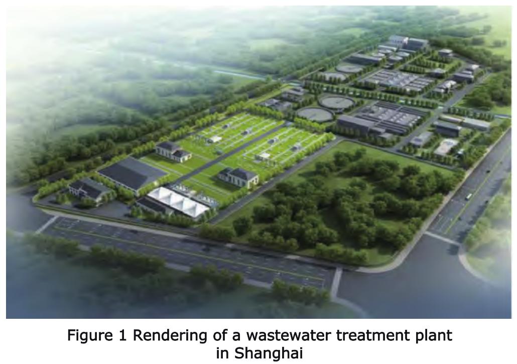
With prolonged operation, the aeration system has experienced significant pipeline aging and mechanical wear. Frequent equipment failures and insufficient aeration have compromised the stability of effluent quality. Therefore, upgrading the aeration equipment and process is necessary to achieve efficient, energy-saving, and stable wastewater treatment. The plant must continue operating during the retrofit to avoid impacting domestic sewage discharge, necessitating a non-shutdown retrofit with strict timeline requirements. By analyzing the plant's treatment capacity and selecting periods of lower flow for partial shutdowns, the retrofit was carried out without halting operations. A rendering of the wastewater treatment plant is shown in Figure 1.
1. Analysis of the Current Aeration System and Retrofit Necessity
Before the retrofit, on-site inspections revealed that long-term operation of the biological reaction tank aeration system had significantly reduced aeration efficiency and caused uneven aeration distribution. This was evidenced by the settling of flocculent matter in the water, affecting treatment performance. The external air main header of the Phase I biological reaction tanks, due to extended service, suffered severe corrosion, with extensive rust and perforations leading to air leakage and unstable oxygen supply. Furthermore, aeration at the distal ends of the pipelines was notably insufficient, exacerbating the uneven aeration issue. To ensure adequate aeration, standby centrifugal blowers had to be frequently activated, increasing energy consumption and deteriorating effluent quality. Aeration system failures reduced treatment efficiency, causing effluent to fail to meet the required standards.
These issues severely constrained the plant's normal operation and treatment efficacy, making an urgent upgrade necessary to address problems such as declining aeration efficiency, high energy consumption, deteriorating effluent quality, pipeline damage, and uneven oxygen supply. The goal was to ensure the plant's efficient, stable, and economical operation.
2. Aeration System Retrofit Plan
3.1 Determination of Retrofit Scope
Based on the identified aeration system problems and through communication with the operation management unit and design institute, the following retrofit scope was determined:
(1) Replacement of Tubular Diffusers. After prolonged use in the aerobic zones of the Phase I and II biological reaction tanks, the membrane elasticity of the tubular diffusers had weakened. Aging and damage to membranes, gaskets, or connections, clogging of diffuser orifices, and biofilm accumulation on diffuser surfaces and pipeline interiors caused diffuser ballooning, gas leakage, and uneven bubble release, reducing aeration efficiency.
(2) Replacement of aeration distribution laterals. Long-term exposure of diffusers and pipelines to corrosive wastewater led to corrosion, with resulting rust debris exacerbating orifice clogging.
(3) Addition of aeration main header ring pipe. The original design of the biological reaction tank aeration system featured only a single main header with laterals connected in series. This resulted in different pressures at the beginning and end laterals, causing uneven aeration within the tank. Therefore, a stainless steel air ring main header was added to achieve more uniform aeration.
3.2 Retrofit Sequence Planning
3.2.1 Timing Sequence Planning
During the retrofit, it was essential to ensure the continuous normal operation of existing facilities, imposing extremely high demands on schedule control.
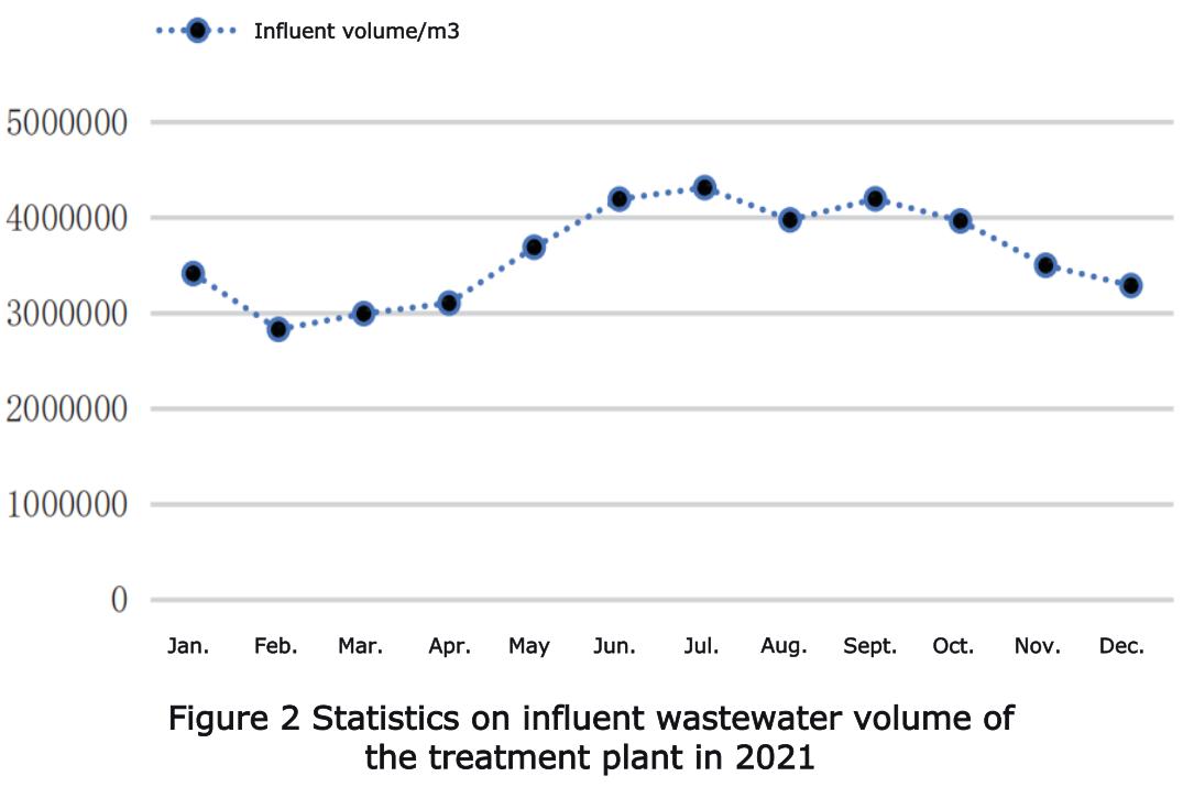
Part of the plant's influent comes from older residential areas with combined sewer systems (mixing stormwater and sewage). During the flood season, domestic wastewater discharge increases substantially. Conducting retrofit work during this period, which involved reducing some treatment capacity, could affect the stable operation of existing facilities, making it difficult to handle peak discharge loads and increasing operational risks. Statistical analysis of the plant's wastewater treatment volume data from the previous year (see Figure 2) indicated that the non-flood seasons, specifically November-December and February-April when treatment volumes are lower, were suitable for the retrofit. This timing helped ensure continuous and effective treatment of domestic wastewater while creating a relatively stable and controllable construction environment, guaranteeing project progress.
3.2.2 Spatial Sequence Planning
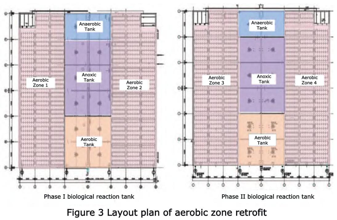
The biological reaction tanks at this plant have four aerobic zones (see Figure 3). To ensure safe and reliable plant operation, an analysis of the current treatment status led to adopting an "operate 3, retrofit 1" mode. This ensured the continuity and stability of overall wastewater treatment functionality during the retrofit.
The upgrade proceeded sequentially from Aerobic Zone 1 to Aerobic Zone 4. During the retrofit of each aerobic zone, components like tubular diffusers and air distribution laterals were replaced. The other three aerobic zones remained operational, handling the full treatment load to ensure uninterrupted wastewater processing. After completion, rigorous commissioning and acceptance testing were conducted before restoring the retrofitted zone to normal operation, followed by moving to the next zone.
By implementing this "operate 3, retrofit 1" phased construction strategy, the upgrade of all four aerobic zones was completed in an orderly and efficient manner. This approach minimized safety risks and environmental impacts during construction while ensuring the plant's continuous operation without affecting domestic sewage discharge.
4. Retrofit Implementation
4.1 Desludging of Aerobic Tanks
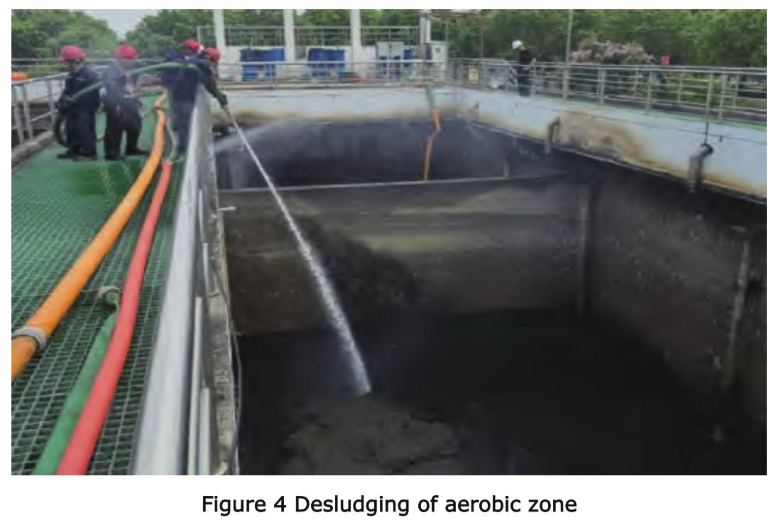
Before modifying the aeration pipes in the aerobic tanks, desludging was necessary to remove accumulated sludge, debris, and potentially harmful gases from the tank bottom. This provided a safe and accessible working environment for aeration pipeline construction. The procedure involved: First, closing the tank inlet valve before desludging to cut off incoming flow. Warning signs were posted in the work area for safety. Desludging began by using pumps to drain wastewater and upper-layer sludge from the tank, lowering the liquid level as much as possible. High-pressure water jets were then used to repeatedly flush and dilute the settled sludge until most was removed (see Figure 4). The resulting slurry was pumped to sludge-water separation equipment. After sludge thickening, conditioning, and dewatering, it was transported off-site for disposal.
For corners or residues inaccessible to machinery, manual entry and detailed cleaning were performed. Before entry, forced ventilation equipment ensured continuous air circulation to reduce hazardous gas concentrations. Portable multi-gas detectors monitored toxic and harmful gases, and animal tests were conducted to confirm safety before entry. During work, safety supervisors were present, and personnel wore respirators, protective suits, safety goggles, and gloves, with rescue equipment on standby.
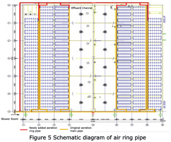
4.2 Air Main Header Retrofit
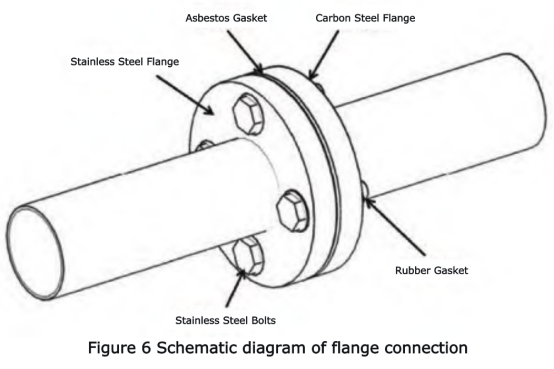
To address the pressure differential between the beginning and end aeration laterals, a stainless steel air ring main header was added, forming a loop with the end of the original air main header (see Figure 5). This ensured consistent air supply pressure to terminal units as to front-end units, promoting more uniform aeration. The new aeration main header, constructed of stainless steel pipe, was buried approximately 1 meter underground and connected to the original air main header via flanges. High-temperature-resistant asbestos gaskets were used for sealing between flanges, secured with stainless steel bolts and nuts. To prevent galvanic corrosion between the stainless steel bolts/nuts and adjacent carbon steel components, rubber gaskets were placed between the bolts and flanges (see Figure 6).
4.3 Fine Bubble Diffuser and Aeration Lateral Retrofit
(1) Incoming Inspection and Storage. Upon delivery, both the external and internal components of the fine bubble diffusers were inspected, with particular attention to the rubber membranes and stainless steel clamps for any damage. Diffusers and accessories were stored indoors in a dry, ventilated area, protected from freezing, overheating, direct sunlight, dust, mineral oils, and hydrocarbons. For on-site storage, oil-coated waterproof tarpaulins were used to cover materials, preventing UV radiation damage.
(2) Construction Preparation. While tank wall corrosion protection and tank bottom desludging were underway, external removal of original aeration pipes and installation measurements were conducted simultaneously. This maximized use of the available work window, shortening the construction period and improving overall efficiency. Based on measurements and design drawings, economically durable and easy-to-install/maintain ABS plastic pipes were selected to replace the stainless steel laterals. The aeration laterals were cut and perforated in the factory using specialized equipment to ensure symmetrically distributed, identically sized and shaped orifices, guaranteeing installation quality. Orifice diameter was φ28mm, with a tolerance of ±0.1mm and a vertical direction tolerance of 0.5mm.
(3) Aeration Lateral Retrofit. After complete removal of the original stainless steel aeration distribution laterals from the tank bottom and thorough cleaning of debris, the new aeration laterals were installed. The new aeration distribution pipes were connected to the original stainless steel aeration main header via flanges. Aeration laterals needed to be leveled. To compensate for unevenness of the concrete tank bottom, adjustable-height pipe supports were installed under the distribution pipes.
(4) Pipeline Purging. After installation of the tank bottom aeration lateral network and before installing the fine bubble diffusers, the pipeline system underwent thorough purging to ensure cleanliness. First, all lateral inlet valves were closed. Blowers were started to deliver maximum airflow to the aeration tank. Valves were opened sequentially according to the aeration unit order, using maximum airflow to purge the pipelines and remove debris, preventing clogging or damage to the aeration pipes. After purging, fine bubble diffusers were installed.
(5) Fine Bubble Diffuser Installation. Before installation, diffuser model, specifications, and certificates were checked to ensure quality compliance with design and construction requirements. A strict clean water aeration test was conducted to check for membrane leaks, secure attachment of the diffuser tube membrane, and uniformity of generated bubbles. During installation, two diffuser pipes were directly butted together at the symmetric orifice positions on the pipe. The two locking positions at the pipe head located and secured the connection. Stainless steel bolts and nuts were used for fixation from top and bottom, tightened with a torque wrench to 15 N·m. During tightening, force was applied evenly to the upper and lower parts of the saddle. The level error of all diffuser pipe upper surfaces was strictly controlled within ±5mm to ensure uniform air distribution, prevent local overloading, and guarantee stable equipment operation.
4.4 Commissioning of the Aeration System
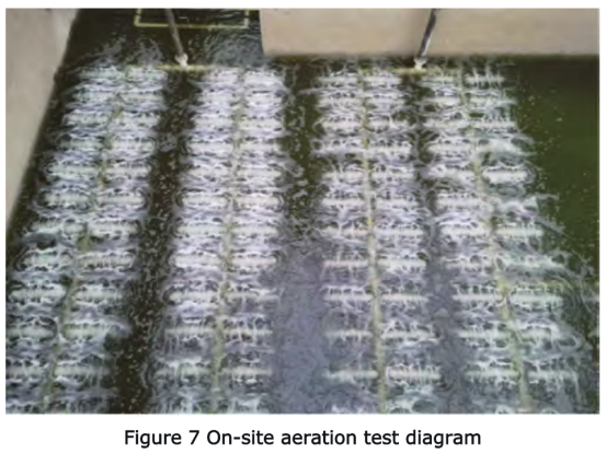
After aeration system installation, a 100 kg concentrated load test was performed on the tank bottom air main header under dry conditions. The header showed no bending deformation, simulating potential heavy loads during actual operation to verify its load-bearing capacity and structural stability. After passing the load test, blowers were started, and lateral valves were opened one by one. Soapy water was sprayed on pipe joints to check for leaks. Upon passing this check, clean water was filled into the tank. During filling, diffuser surface heights were observed and adjusted to be level within an error of no more than ±5mm. When the water level exceeded the diffuser pipe centerline by 200mm, water inflow stopped, and aeration commenced for 5-10 minutes to check all pipe joints for leaks. If localized high airflow was observed, it indicated potential pipeline leaks or diffuser damage. Finally, the diffusers were operated at a medium air rate to check for uniform aeration (see Figure 7).
5. Retrofit Results
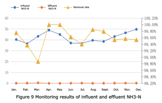
After completing the biological reaction tank aeration system retrofit, the COD and ammonia nitrogen (NH₃-N) content in the tank wastewater were monitored continuously for 12 months to evaluate the retrofit's effectiveness.
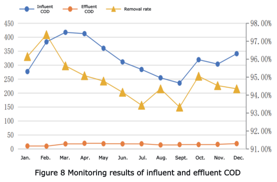
5.1 Influent and Effluent Water Quality
After the aeration tank retrofit, the treated effluent COD stabilized around 16.41 mg/L, with a removal rate consistently above 93% (see Figure 8). Ammonia nitrogen (NH₃-N) levels were below 0.5 mg/L, averaging 0.16 mg/L, with removal rates essentially reaching 99% or higher (see Figure 9). Compared to effluent quality during the same period before the retrofit, all indicators showed significant improvement, demonstrating markedly enhanced removal efficiency for various pollutants.
5.2 Post-Retrofit Activated Sludge Condition
Before the aeration system retrofit, insufficient aeration and oxygenation caused activated sludge to become anoxic, leading to problems like blackening sludge, foul odors, turbid supernatant, and poor effluent quality. Implementing measures such as adding the aeration ring pipe and replacing fine bubble diffusers and laterals ensured adequate oxygen supply. This allowed aerobic microorganisms in the activated sludge to access sufficient oxygen for effective organic matter decomposition, improving treatment efficiency. The supernatant in the aeration tanks became clear, sludge color changed to a healthy tan, odors significantly reduced, and floating foam greatly diminished. These observations indicate the aeration system retrofit achieved the expected outcomes.
6. Conclusion
This study investigated non-shutdown retrofitting technology for wastewater treatment plant aeration systems, focusing on the planning and implementation of such retrofits.
(1) Pre-retrofit planning is crucial. This involves analyzing existing aeration system problems to develop a targeted retrofit plan. Understanding local discharge patterns is key. By reviewing historical data, conducting real-time monitoring, or communicating with relevant departments, peak and low-flow periods can be identified precisely. Scheduling retrofit work during low-flow periods minimizes impact on wastewater treatment, ensuring stable and safe plant operation.
(2) Technical challenges during the retrofit process, including desludging, aeration lateral and fine bubble diffuser modification, and commissioning, were analyzed and summarized. Before modifying the in-tank aeration system, careful removal of bottom sludge is necessary to facilitate subsequent construction and prevent hazardous gas generation.
(3) For the construction of fine bubble diffusers and laterals, meticulous planning and control are required across all stages: material selection, storage, installation, construction, and commissioning. This ensures uniform aeration and maintains sludge activity. For similar aeration system retrofit projects, close attention should be paid to local discharge dynamics to scientifically determine construction timing. In designing construction and testing schemes, achieving system functionality must be balanced with economic considerations, selecting the implementation plan that best aligns with the project's overall benefits.
Media Contact
Company Name: Hangzhou Juntai Plastic Products Co., Ltd.
Email: Send Email
Country: China
Website: https://www.juntaienviro.com/