
DONGGUAN, CN / ACCESS Newswire / November 19, 2026 / A medical equipment keypad has to remain readable after cleaning, respond to a gloved hand and connect correctly to the electronics behind it. Those demands converge in a component that may occupy only a small part of the device. For the equipment manufacturer, however, an unsuitable surface film or a poorly positioned circuit tail can mean revisiting a design that appeared complete on screen.

Jasper Electronics Co., Ltd. (JASPER) addresses these issues through custom membrane switch design review, prototyping and manufacturing in Dongguan, China. Established in 2006, the company works with original equipment manufacturers (OEMs) to coordinate the visible control panel with its underlying circuit and the enclosure into which it will be installed.
Its medical membrane switches can incorporate tactile or non-tactile keys, display windows, lighting and shielding. Each project begins with the intended use of the equipment. The cleaning procedure, operator requirements and installation details guide the construction, giving the device team a sample it can evaluate against its own specification.
This connection between application and production is central to JASPER's offering. A drawing review establishes what needs to be built; printing, lamination and inspection carry those decisions into the finished part. For medical OEMs, the value lies in resolving the details that otherwise fall between the graphic designer, electronics engineer and assembly team.
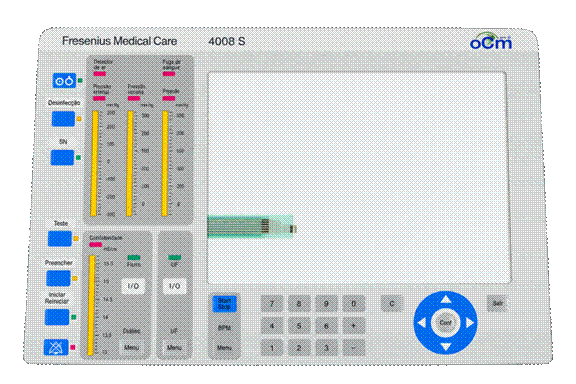
The front panel brings several design disciplines together
Medical membrane switches provide a low-profile way to combine printed instructions and electrical controls on the front of a device. A continuous graphic surface can cover several keys, with the switch contacts and circuit arranged underneath. This gives the equipment designer control over the panel outline, key positions and visual grouping without having to place a separate exposed button housing around every function.
A patient-monitoring interface may need clearly separated function keys beside a display. A laboratory analyzer may require numeric entry and a window that remains readable under overhead lighting. On portable equipment, the available grip and the reach of a thumb can influence the arrangement of controls. These are different design problems, even when the panels use similar materials.
JASPER's custom membrane switches allow the outline, printed graphics and electrical layout to be developed around the equipment. A display opening can sit alongside grouped controls, while a flexible tail carries the connection to a board elsewhere in the enclosure. The available space and assembly sequence determine how those features fit together.
Cleaning exposure reaches beyond the outer film
Repeated cleaning puts the front panel under conditions that a static product photograph cannot show. The outer film is exposed directly, but liquid can also reach an edge, a window border or the point where the circuit tail leaves the assembly. Material selection therefore has to account for the whole construction.
Polyester (PET) and polycarbonate (PC) are established overlay options. Hardcoated PET is a candidate where repeated flexing, abrasion and chemical exposure need to be considered together. PC offers different appearance and processing properties. The film grade, surface finish and adhesive must suit the application; choosing between the two material names is only the beginning of that decision.
JASPER's application review brings the intended cleaning product, concentration, contact time and frequency into the discussion before the panel construction is finalized. These inputs help define both the material choice and the way the sample will be evaluated. A wipe-down procedure, for example, creates different exposure conditions from immersion, particularly around the perimeter and tail exit.
A hazy window can obscure information even while every key still functions. An edge beginning to lift may not affect a basic continuity check. Testing the bonded panel under the specified cleaning procedure reveals these changes, allowing the OEM to assess the combination of film, print and adhesive that will be used on its equipment.
Key feedback is shaped by the complete construction
For a gloved operator, the feel of a key comes from several layers working together. The overlay, embossed area, tactile element and support beneath the circuit all affect the response. Key spacing matters too: a distinct click is of limited help if neighboring controls are difficult to distinguish by touch.
A metal dome provides snap-action feedback. A non-tactile construction has no mechanical click, so the equipment can provide confirmation through its display or an audible response. Neither arrangement settles the interface design on its own. The size and position of each key still have to suit the operator's task and the intended gloves.
JASPER can incorporate custom key shapes, printed grouping and embossed areas into the panel. The artwork gives frequently used controls a visible identity, while the physical sample reveals whether their position and feel work in practice. Contrast and recognizable symbols support the layout without relying on color alone to communicate a function.
A loose keypad sample is useful, but installation can change its feel. The support provided by the enclosure and the way the panel is bonded become part of the operating experience. Reviewing the sample in that position connects the manufacturer's component work with the OEM's assessment of the complete interface.
The connection behind the panel matters as much as its layout
A finished front-view drawing can conceal an installation problem. The panel may fit its recess while the tail reaches the connector from the wrong direction. JASPER's design review includes adhesive coverage, recess depth and connector access so these details are considered alongside the visible layout.
The enclosure material and surface finish influence adhesive selection. Window borders and tail exits also need room for the intended sealing detail. Where ingress protection is required, the housing and attachment method form part of the assembly being evaluated. The front surface alone does not determine what happens at these junctions.
Tail length, contact side and pin order have to match the receiving electronics. Access can become more difficult once neighboring assemblies are fitted. Reviewing that sequence while the tail layout is still being developed gives the equipment team an opportunity to resolve the connection before it becomes an assembly-line problem.
JASPER offers printed flexible circuits, copper flexible printed circuit (FPC) assemblies and printed circuit board (PCB) constructions. These provide different options for routing, support and component placement. Where shielding is included, a defined connection to the equipment ground is part of the design, alongside the signal circuit.
Lighting adds another relationship to manage. An illuminated legend needs to line up with the intended light source, while a clear or tinted window must align with the display. The sample brings these features together so the team can examine brightness, viewing position and mechanical fit in the same assembly.
Drawing review links the design to the factory
Design for manufacturability (DFM) connects the drawings to the way the part will be built. JASPER reviews the artwork, circuit and layer construction before tooling. A proposed feature can then be considered against printing, forming and assembly requirements while changes are still relatively straightforward to make.
The company's membrane switch manufacturing capabilities include screen printing, lamination, assembly and inspection. This makes the interaction between processes relevant at the drawing stage. A narrow printed border needs to accommodate registration tolerance around the display opening beneath it. An embossed key needs space to form without interfering with an adjacent window or bonded edge.
A connector drawing viewed from the wrong side can reverse the intended pin assignment. An artwork revision can move a key while leaving its circuit contact in the original position. Such mismatches are easier to identify when the files are reviewed together, before they become separate instructions for production.
For purchasing teams, the resulting specification also defines the quotation. Tooling, sample quantities and inspection requirements can be considered against the same construction. This gives the commercial discussion a concrete basis and helps distinguish a change in price from a change in what is being supplied.
Sampling puts the construction into its operating position
The first physical sample answers questions that separate drawings cannot. It shows whether the panel sits correctly in its recess, whether the connection is accessible and how the keys respond once the assembly is supported by the enclosure. The window and indicators can also be viewed from the operator's position.
The checks answer different questions. Dimensions and circuit connections establish whether the sample matches the drawing. Cleaning exposure, repeated actuation and environmental evaluation examine how the selected construction behaves under the planned conditions. JASPER's medical interface process includes agreeing these acceptance checks with the OEM before the sample is approved for production.
JASPER's typical schedule for standard prototypes is 7-10 days, with timing confirmed for the agreed tooling, materials and project scope. The sampling period gives the OEM a physical construction to assess; the acceptance plan determines the evaluation required before production release.
Once the remaining construction details are resolved, the approved drawing and sample become the references for the production build. This handover connects the development work to the part that will actually be ordered and installed.
Electrical and visual inspection examine different risks
JASPER's manufacturing workflow carries the approved artwork and circuit layout through printing, layer alignment and assembly. Its Class 50,000 cleanroom production environment supports the handling and lamination of the layers, where trapped particles can affect visible surfaces or display windows.
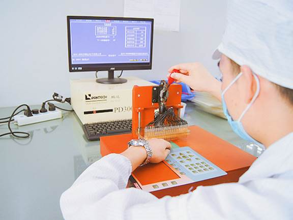
Alignment also has a functional role. The graphic overlay, spacer and circuit have to place each key over its intended contact area. An error between layers can affect the result even if each layer looks correct when inspected separately. The agreed construction provides the reference through these assembly steps.
Electrical inspection checks connections against the approved circuit and pinout, including continuity and open or short conditions. It addresses faults that cannot be identified by looking at the finished panel. A neatly printed key legend says little about whether the associated circuit reaches the intended connector contact.
Visual inspection covers a separate set of characteristics. Printed legends must be legible, window areas clear and the assembled layers aligned with the approved reference. Marks or contamination on a display window may have no effect on a continuity result but still make the part unsuitable for installation.
The electrical test and visual check serve different purposes. A circuit fault calls for investigation of the conductive path or connection; a print or window defect calls for examination of the surface and assembly. Keeping both in the inspection process helps identify which part of the construction needs attention.For medical equipment manufacturers, consistent identification matters after the parts leave the factory as well. Part numbers, drawing revisions and agreed inspection records help distinguish the approved construction from an earlier sample or a similar-looking variant. Packaging protects the contact areas and cosmetic surfaces on their way to the equipment assembly team.
Support for new designs and existing equipment
A new device and a replacement panel present different starting points. A new design may leave room to adjust key positions or the tail exit. An existing instrument may have a fixed recess and connector that the replacement has to match. JASPER accepts drawings, existing samples and marked-up photographs as references for this review.
Development quantities and expected repeat orders give that discussion its commercial context. They inform planning for the sample build and subsequent production, alongside tooling and the documentation required with the parts. A clear specification lets engineering and procurement review the same project without reducing it to a photograph and a unit price.
For repeat production, the approved configuration remains important when changes are proposed. A replacement film or adhesive can affect the appearance, bond or response established during sampling. Reviewing the substitution against that reference gives both teams a basis for deciding what needs further evaluation before the revised part reaches the equipment build.
JASPER's focus is the connection between these stages: understanding the device requirements, building the sample and carrying the agreed construction into production. For medical OEMs sourcing a custom keypad or control panel, the company offers a starting point for that discussion through drawing and sample review. Engineering and purchasing teams can submit their interface requirements to begin a project-specific quotation.
About Jasper Electronics
Founded in 2006 in Dongguan, China, Jasper Electronics Co., Ltd. manufactures custom membrane switches and related interface products for OEM equipment. Its product capabilities include graphic overlays, silicone rubber keypads and HMI assemblies. JASPER supports projects through drawing review, prototyping, printing, assembly and inspection, with a focus on matching the interface construction to the equipment application.
Company Information
Company - Jasper Electronics Co., Ltd.
Contact Person - Hu Zhou
Email - welcome@jasperele.com
Phone - +86 136 3262 5290
Country - China
City - Dongguan
Website - www.jasperele.com
SOURCE: Jasper Electronics Co., Ltd.
View the original press release on ACCESS Newswire